The RS485interface uses a differential transmission method. The communication betweenthe nodes is through a pair (half-duplex) or two pairs (full-duplex) twistedpair as the transmission medium. According to the RS-485 standard, thereceiver's receiving sensitivity is +200mV, that is, when the differentialvoltage at the receiving end is greater than or equal to 200mV, the receiveroutputs a high level; when it is less than or equal to 200mV, the receiveroutput is low; The receiver output is indeterminate between 200mV. RS-485 datahas a maximum transfer rate of 10 Mbps. The RS-485 interface is a combinationof balanced driver and differential receiver, which has enhancedanti-common-mode interference capability, that is, good anti-noiseinterference. The maximum transmission distance of the RS-485 interface is 4000feet, which is actually up to 3000 meters. The RS-485 interface allows up to128 transceivers to be connected on the bus. The RS-485 interface has goodnoise immunity, long transmission distance and multi-station capability, makingit the preferred serial interface. . Because of the half-duplex networkcomposed of RS485 interfaces, generally only two connection lines are needed,so the RS485 interfaces are all transmitted by shielded twisted pair.
When selecting the485 chip, pay attention to its ESD protection capability, drive capability, anddefinition of the 485 bus differential signal. Taking the SN65176 and SN75176as examples, the SN65176B and SN75176B differential bus transceivers aredesigned for integrated circuits for bidirectional data communication onmulti-node buses. The SN65176B and SN75176B combine a tri-state differentialline driver with a differential input line receiver, both operating from a single5V supply. The driver and receiver have high and low enable, respectively,connected together as an external function for direction control. When thedrive disables the bus or VCC = 0, the driver's differential output andreceiver differential input connections form a differential input/output (I/O)bus internally designed to provide the lowest load port. These ports have awide range of positive and negative common-mode voltages, making the devicesuitable for serial line applications.
The driver is designedfor current sources up to 60 mA and features positive negative current limitand thermal shutdown line fault protection. The thermal switch design isoccurring at a temperature of approximately 150 °C. The receiver features aminimum input impedance of 12 KΩ, a 200 mV input sensitivity, and a 50 mVtypical hysteresis input at the input.

The SN75176application circuit diagram shows that, first, the A/B line needs to be pulledup/down to ensure that the A/B differential signal is still in a certain statewhen the bus is idle, to avoid noise effects. When the upper/loweringresistance is obtained, the load is increased, which will affect the number ofnodes on the 485 bus; if it is large, it will affect the baud rate of datatransmission. Generally between a few K to tens of K, the specific needs of theapplication circuit. For example, the upper/lower pull value of this circuit is10K. In the actual load test (1200bps), only a dozen loads can be hung on the485 bus. When it is changed to 47K, it can be hung to more than one hundredloads; To communicate at 9600 bps, the upper/lower pull is smaller. Second, theground TVS is used as ESD protection. Third, try not to drive the load above orbelow. It is best to use one signal to control the enable (ie P1.0) to fullyutilize the IC's drive capability. Fourth, due to the industrial applicationfield, it is possible to connect many nodes at the same time on the 485 generalroute. At this time, the external output current of the A/B line will berelatively large. If the output of the front-end power supply circuit of the485 chip is not enough, the differential voltage is insufficient and thecommunication cannot be performed normally. Therefore, it is necessary toensure that the RS485 output capability is sufficient.
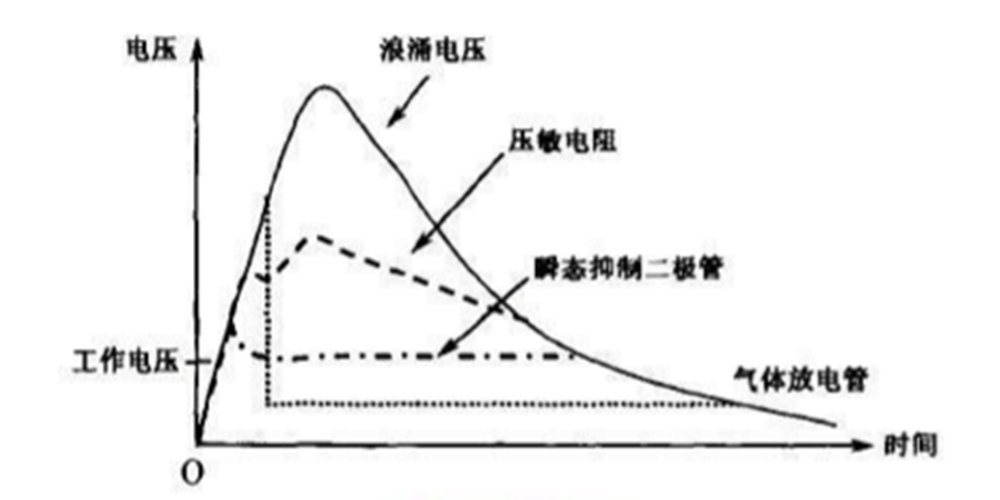
RS485 portprotection mainly includes static protection (ESD protection), surge protectionand lightning protection. The most important feature of lightning surges is theextremely high energy, so special protective devices are needed: transientsuppression diodes, varistors and gas discharge tubes. As shown in the figure,the voltage waveform of the surge through different suppression devices.
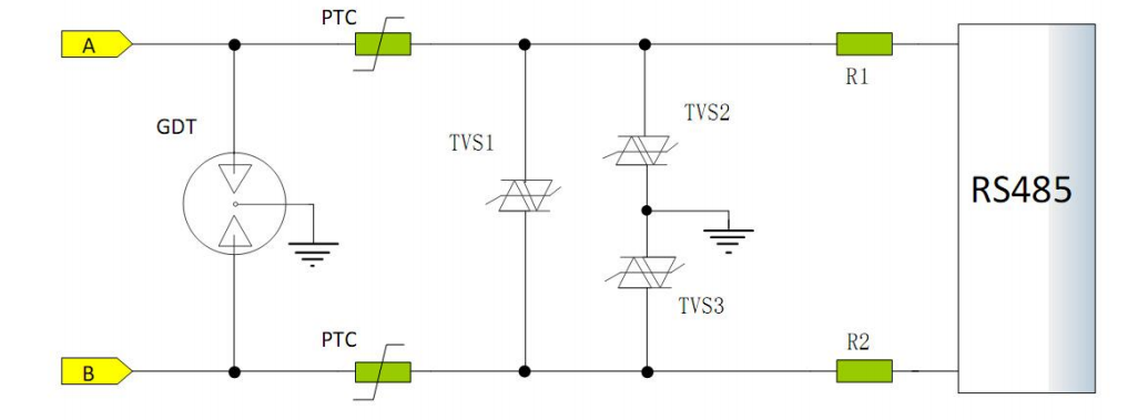
 Voltage waveform when a surge passes through different suppression devices RS485 port protection using these threeprotection devices, as shown:

ESD protection:Taking SN65176 and SN75176 as examples, the chip itself has a certain ESDprotection level, and the system requirements are 8KV contact discharge and15KV air discharge. In this case, it is necessary to add TVS to the groundbetween the A/B lines to protect the chip. TVS1, TVS2, TVS3. Note that the TVStube should use high-speed, low-capacity, and large-pass flow as much aspossible. The starting voltage and cut-off voltage should be properly selectedto prevent TVS from malfunctioning and interfere with the normal communicationof 485 (also taking into account the common-mode voltage on the 485 bus).
Surge protection:Taking this circuit as an example, a two-way PTC (varistor) + TVS tube forms aloop. When a large AC voltage is injected, the PTC starts to generate heat andform a high resistance to protect the subsequent circuit. The varistor (PTC)consists of a metal oxide (mainly zinc oxide) material and is a clamp-typedevice. Its characteristics are very similar to those of two back-to-back Zenertubes, with a response rate of nanoseconds. The varistor's ability to absorbtransient signals is proportional to its volume: its thickness is proportionalto the voltage; the area is proportional to the current. Varistors arecurrently the most widely used surge suppression devices in electronics.
Lightningprotection: Industrial grade DTU requires lightning protection. Take thiscircuit as an example. GDT and TVS are added to the ground between A and Blines to protect the circuit. In the DC circuit, the nominal voltage of the gasdischarge tube is selected to be 1.8 times the operating voltage; in the ACcircuit, it is selected to be 2.5 times the effective value of the operatingvoltage. The nominal current capacity of the gas discharge tube should begreater than the maximum surge impact capacity of the protected circuit.
In fact, ESDprotection, surge protection and lightning protection are mainly achieved bysuitable devices and reasonable PCB layout.
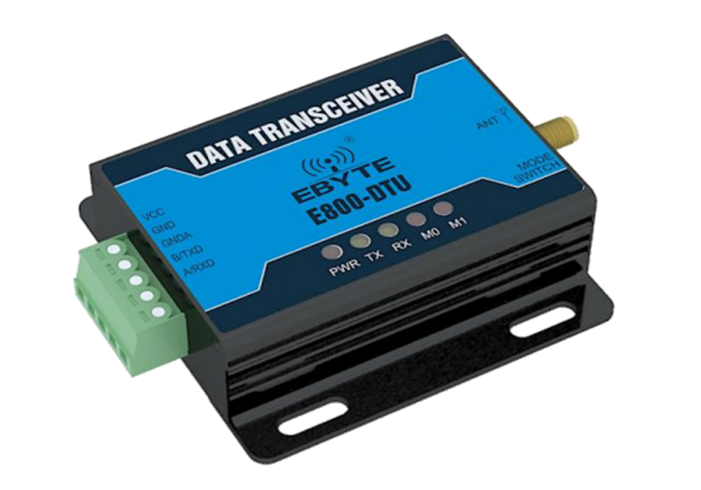
Products with 485 ports have been widely used insecurity, surveillance, access control, smart home and industrial control, suchas Chengdu E-Technology's wireless data transmission E800 series DTU, its 485port is made of industrial-grade isolation and protection The application isvery extensive.
