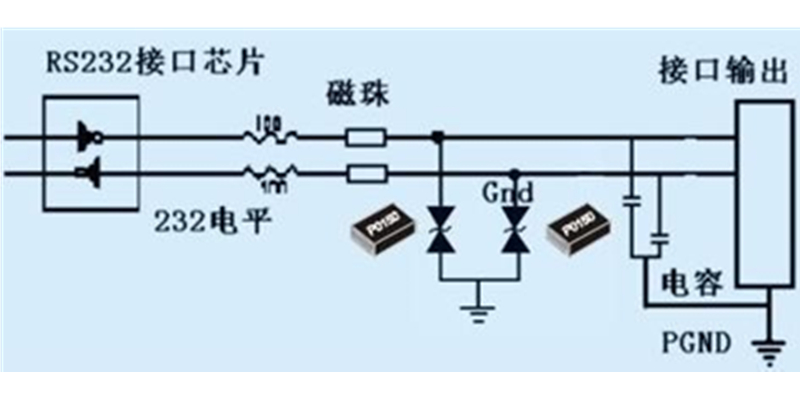
First, theprotection of RS232 port
1, design concept
The RS232 port is a port that is often used in communication. Generally, thedata transmission distance cannot exceed 15 meters, and it is often charged andplugged and unplugged. This causes the port to receive an overvoltage andovercurrent impact caused by multiple operations. Damage to the chip andequipment, so that the production cost, the production cycle increases.Protection of the RS232 port is a must.
2, the output voltage
The output voltage of the RS232 interface chip is generally ±9V, which does notexceed ±12V. Therefore, the bidirectional transient suppression diode BS0150MScan be used for the interface signal transmission and reception line, and a 100ohm resistor is used as the current limiting resistor. As shown in the figure,in order to ensure that the resistance is not burned, the power of the resistorshould be selected to be more than 1/4W.

Second, RS485interface protection circuit
1. Necessity of lightning overvoltage protection:
The RS485 bus can realize long-distance transmission of more than 1200 meters.In actual use, the lines are usually outside, and the lightning is likely tocause excessive voltage in the thunderstorm, so that the chip is burnt.Usually, the operating voltage of the RS485 chip is about 5V, and the withstandvoltage of the chip is -7~+12V. If overvoltage is introduced, the chip will bebroken down and cause damage. If there is a strong surge energy, it may causethe device to burst and the PCB board is burnt.
2, protection methods and schematics:
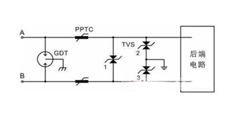
As shown in the figure is a two-stage protection circuit diagram of the RS485port. When the device is struck by lightning, the overvoltage caused by it willbe introduced into the circuit from both ends. Then our GDT is the first levelof protection. At this time, the overvoltage will be reduced to a few hundredvolts, and then the PPTC limit. Wave, TVS is the secondary voltage-limitingprotection, so that the voltage to the back-end circuit is clamped at about 8V,thus achieving protection of the back-end circuit. TVS2/TVS3 is used for commonmode protection, and TVS1 is used for differential mode protection.

3, the standardof protection
We have a standard for overvoltage protection: IEC6100-4-5, ITU-T K20/K21 andGB9043 have test standards for lightning surge immunity. The highest teststandard for its communication line is 10/700μS, 4KV. 10/700μS is the lightningvoltage waveform induced in the communication line, which means that the valuerises from zero to peak time is 10ms, and drops to half of peak value is 700μS.
The protection of lightning surges must first use a relatively high-qualityprotection component. The design of the PCB circuit board should be reasonable,and the most important one is grounding. It is often required to directly use a10 ohm resistor to directly access the earth. Reliable grounding can greatlyimprove the protection effect, and poor grounding will greatly reduce theprotective effect.
We can't use only one level of protection in order to reduce cost and size.Because the device capable of withstanding large energy lightning strikescannot clamp the lightning strike voltage to the level that the chip canwithstand at one time, the TVS can clamp the lightning strike voltage to thelevel that the chip can withstand, but cannot withstand large lightning strikeenergy, so it must be two levels. Protection.
Third, thedifference between RS232/RS422 and RS485 protection
The protection method is exactly the same. The voltage parameters of the fineprotection device TVS should be chosen differently depending on the operatingvoltage. If the maximum working voltage of RS232 is 15V, then TVS is selectedas P6KE18CA or patch SMBJ15CA, RS422 maximum working voltage is 12V, then TVSis selected as P6KE15CA or patch SMBJ12CA
The main cause of 485 interface damage is due to transient overvoltage andstatic electricity. The causes of transient overvoltage and static electricityare many and complicated. Therefore, the EIA-485 standard requires that thesignal ground of each RS485 interface be connected with a low resistance wire.Together to ensure that the ground potential of each node is equal, eliminatethe ground loop.
When the unconnected connecting cable is plugged and unplugged, there are manydevices such as inductors and capacitors in the circuit with unequal potentialsat both ends. Transient overvoltage or overcurrent is inevitable when theplugging and unplugging occurs.
Transient overvoltages or overcurrents generated by other devices connected tothe RS485 bus will also flow in. The more devices connected to the bus, themore transient overvoltages are generated.
Fourth, the solution is too large
When the communication line is long or the outdoor overhead line, lightningwill inevitably cause overvoltage on the line, and its energy is often huge.Solution:
1. The TVS diode should be placed close to the interface and the current-limiting(matching) resistor should be close to the chip.
2. Select the high-speed RS485 chip with perfect protection measures such asstatic protection, overheat protection and input failure protection.
3. Using a new type of protection device TVS or ceramic surge absorber withfaster response and greater transient power, such as LT-BS0080MS, 2KV 10/700uS,broadband optimized protector LT-B3D420L can fight more than 5KA Current surge.